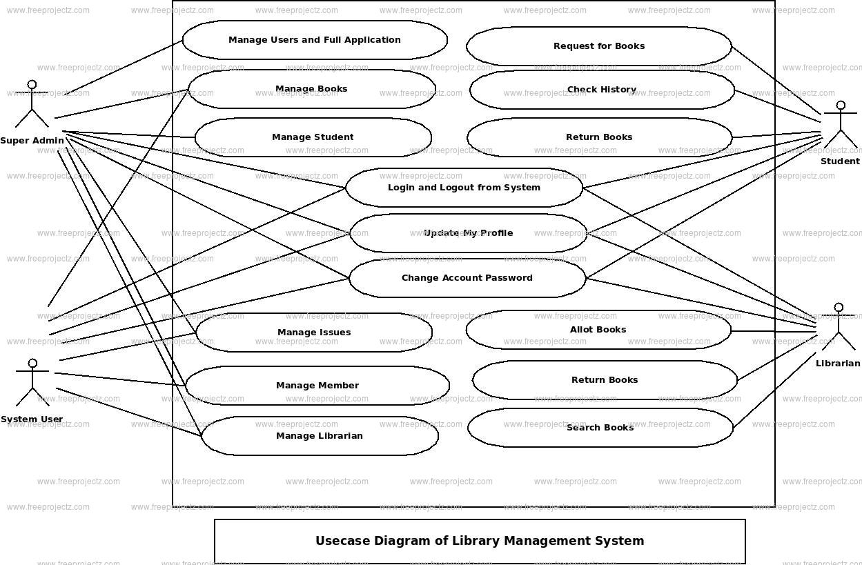

Test cases and wireframes can be developed based on the defined use cases. Entity-relationship diagrams or ER diagrams are used to showcase the relationships developed between objects or entities in a system. Use case driven approach can lead you all the way from analysis to design, and subsequently to development and testing:ĭeveloping a problem statement for the target systemĬapturing requirements - Use case identification (scoping and partitioning of the problem into a set of functional requirements)ĭetailing the event flow for each use case (from analysis to design)īased on the event flow, we can develop a sequence diagram to represent each use case scenario.īy refining the system-level sequence diagram into a more detailed MVC sequence diagram, we can divide the system functionality into 3 layers of reusable software architecture that serves as a clear implementation specification.īy integrating the sequence diagrams of the corresponding use cases, we can identify the set of candidate objects required for the implementation of system functions (use cases) that are currently undeveloped.


The use case model is the conceptual center of the entire SDLC, as it drives every development activity that follows. An ERD contains different symbols and connectors that visualize two important information: The major entities within the system scope, and the inter-relationships among these entities. Why the use case driven approach applies to the entire SDLC? Entity Relationship Diagram, also known as ERD, ER Diagram or ER model, is a type of structural diagram for use in database design. View and play PowerPoint presentations online. use case diagram (UML use case diagram) By TechTarget Contributor A use case diagram is a way to summarize details of a system and the users within that system.


 0 kommentar(er)
